
What Size Air Compressor Do I Need for My Factory?
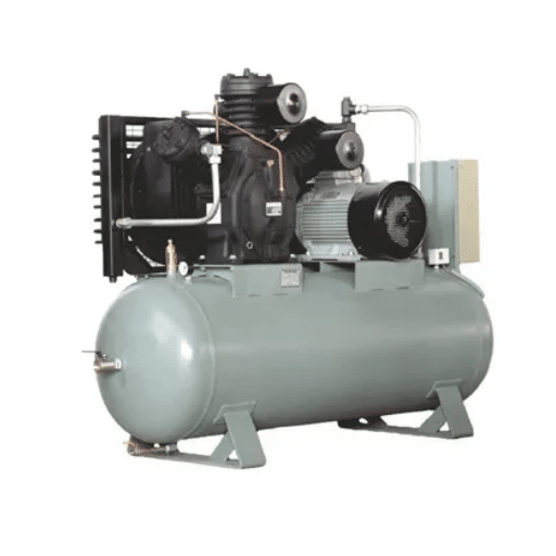
In Jakarta, a production company in the region psychologically bandwagons and purchases a 30 HP air compressor because it was stated that ‘it would be more than enough’. They were, however, actually simultaneous users of only around 45 CFM. The 30 HP unit blew 120 CFM. This was even worse because it turned on and off over and over again, leading to unnecessary energy consumption, and negative impact on the motor. This cost them about $17,000 more for the extra power consumed for a period of six years. An even more glaring obvious point is that a 10 HP machine was overly overrated for the demand.
If you are trying to position your air compressor efficiently in your work cycle, you are a typical client. Most consumers do not have such kind of knowledge and they base their decision on the horsepower of the machine, its price, or a general suggestion provided by the manufacturer. Such an approach in many cases tends to air compressors can be too small or too large and thus simply wastes money.
This article will help you identify the optimum compressor parameters for your operation. You shall find out how best to catalogue the tools in use, determine the true peak demand and incorporate an additional compressor specification. Covering is also dealt with. There are also a few drop-down examples that show three types of plant- a small, medium and a large manufacturing unit.
Why Sizing Matters: The Cost of Wrong-Sizing
What Happens When Your Compressor Is Undersized
A suitably practical compressor operates constantly; however, it is unable to maintain air pressure. Equipment can no longer deliver full torque power. Spray guns work ineffectively in applying paint to the target. The operation speed of valves drop and the machines fail.
The cost is unanticipated and it is not the compressor. It is lost revenue (or potential profit) due to outputs that cannot be produced without electricity. It also includes losses due to rework and including the rush production of the second compressor.
One food packaging factory based in Malaysia added two new sealing machines, designed to be operated with air pressure. The 15 HP compressor in operation was designed for four machines. In such a situation, when there was demand for the operation of all six machines at the same time during the peak period in a noisy factory, the actual suffered the hard consequence and in the process seal gave way spoiling the product and the entire production scheduled for that day got wasted. The cost, $8,200 due to lost production along with extra cost on a compressor purchased in a rush were inevitable.
What Happens When Your Compressor Is Oversized
An oversized compressor does short cycling and stops almost immediately. Every Startup brings a current draw and stretcher. Every Stop throws away energy that is used to build up the pressure. It contributes to faster cooling of the motor. In such a case the model effectiveness decreases.
Energy is the base cost that constitutes 69-75% for the lifetime period of a compressor. It is not uncommon for a 75 kW, mid-size compressor to produce power bills. Even with a ‘mere’ 15% extra capacity, it can exceed $30,000. Safety concerns aside, Oversizing A compressor merely drains out extra energy stockpiled in the power system.
Want to avoid both mistakes? Our complete guide on how to choose an air compressor for your factory covers the full selection framework from demand audit to total cost of ownership.
Step 1: Inventory Every Pneumatic Tool and Machine
If you do not know how many of air driven devices you have, then you will have no idea how big of a power you require. Check all the compressed air consuming devices off one by one.
Hand Tools and Production Equipment
Walk your factory lines and take note of every major tool available which includes impact wrenches, grinders, grinders, drill machines, air sprayers, and cutting tools on hand. Keep track of the manufacturer’s rating for CFM and PSI from the nameplate or user’s manual. If the rating also comes in SCFM (Standard Feet or Cubic Feet per Minute), use that figure directly. The SCFM rating is one that has been corrected to standard conditions and therefore it is the most ideal for comparing tools and compressors.
Factory Automation: Cylinders, Actuators, and Conveyors
Also, do not forget to monitor the automatic machines because they use compressed air. For instance, pneumatic cylinders, linear sliders, work hold systems and air conveyor also use compressed air. The compressor load for each of these depends on the diameter of the cylinder, the length of the stroke and the rate of travel in cycles.
Cycling a 2-inch bore cylinder at 10 times per minute roughly ingests 0.04 CFM of compressed air. Now, a cylinder of the same angle but with a 4-inch bore contributes to the demand of 0.15 CFM. The numbers may seems small, but if you have twenty cylinders operating continuously, they will accrue a significant consumption.
Why Nameplate Ratings Can Mislead You
It is important to remember that the actual airflow rates are slightly higher than those given in the manufacturer’s specifications; this is more so when they assume perfect system conditions. Typically, there is a 10-20% over-consumption caused by worn hoses, governor settings, and hose length. Hence, it is recommended when establishing the collective rate that is peculiar to you to incorporate a slight correction to the manufacturer’s rating.
This table could be used as a quick reference when using typical factory pneumatic tools. All figures are consumption rates of 90 PSI, and some may differ from the values in the original manual of your specific tool.
| Tool | Average CFM | Pressure (PSI) |
|---|---|---|
| Impact wrench (1/2″ drive) | 4-5 | 90 |
| Impact wrench (3/4″ drive) | 6-8 | 90 |
| Air ratchet | 3-4 | 90 |
| Die grinder | 4-6 | 90 |
| Angle grinder | 6-8 | 90 |
| Vertical disc sander | 20 | 90-100 |
| DA sander | 6-9 | 90 |
| Air drill | 4-8 | 90 |
| HVLP spray gun | 8-15 | 40-60 |
| Conventional spray gun | 12-20 | 90 |
| Air hammer | 4-12 | 90-100 |
| Pavement breaker (60 lb) | 60-70 | 90 |
| Sandblaster (small cabinet) | 10-15 | 80-125 |
| Sandblaster (production) | 15-100+ | 100-150 |
| Tire changer | 1-2 | 125-150 |
| Dusting blow gun | 2.5 | 90 |
| Air hoist | 30-50 | 90-150 |
For factory automation, use this cylinder consumption guide at 90 PSI with ten cycles per minute:
| Cylinder Bore | CFM Required |
|---|---|
| 1.0″ | 0.008 |
| 2.0″ | 0.04 |
| 2.5″ | 0.06 |
| 3.25″ | 0.10 |
| 4.0″ | 0.15 |
| 5.0″ | 0.23 |
| 6.0″ | 0.33 |
| 8.0″ | 0.60 |
| 10.0″ | 0.91 |
Step 2: Calculate Simultaneous Demand (Not Total Demand)
This is the point where most consumers make the main mistake. They total every tools the buyer possesses and purchase a machine to accommodate all the items wholesomely.
The #1 Sizing Mistake
Your compressor should not meet the demand of all tools available in the manufacturing premises. But it should be sized to power those tools that are run simultaneously in the max demand condition. For example, using a similar example to the fifty air tools, 8 operators maximum at a time. The compressor is to serve only these 8 operators and the remaining tools,
How to Determine Which Tools Run at the Same Time
Go to your busiest shift. Discover which tools are running after 15 minutes during the maximum hour. Separate the temporary tasks from persistent ones.
Sandblasting for an hour straight though, is considered estimably continuous. When an impact wrench is employed every two minutes for only half a minute or so, this can be referred to continuous.
For tools, which are used sporadically, assign a demand factor. That is, one item that is utilized 25% of the time shall be assigned 0.25 of the compressor rating in your computation. Piston-operated tools, which are utilized at a sustained speed, are treated as 1.0 for the same.
Factoring in Intermittent vs Continuous Use
Whenever you look at making a choice, go to the continuous tools. They are the top end of the cycle. They define the CFM that the compressor must supply at any time, rather than just the maximum. Intermittent tools come to the picture, when the compressors add some air in a short amount of time and carry it to where it is needed. Every compressor and tank system must be capable of handling the highest required air flow rate without a loss in pressure that breaches the minimum.
Run all continuous tools at full CFMs. Run all intermittent tools at their usage/percent factor. Your peak simultaneous demand is the total sum of these two values.
Step 3: Add a Safety Margin for Leaks, Drops, and Growth

In reality, a compressed air system is the result of many factors. They include air leaks, pressure drop along piping, as well as provision for growth, among others.
Why 20-30% Is the Industry Standard Buffer
Multiply your peak simultaneous demand by 1.25 to 1.30. This buffer accounts for:
- System leaks (typically 20-30% of output in an unmaintained plant)
- Pressure drop across dryers, filters, and distribution piping
- Future tool additions or production line expansion
- Seasonal temperature effects on air density
If there is a one-quarter inch leak at 100 PSI, this leak will end up wasting about 100 SCFM. An almost 25 HP compressor, which runs all the time, will have an output capacity of around 100 SCFM. Should a leak still exist, your safety net will not be there as well. It becomes a precautionary measure in case other things don’t work out.
Planning for Future Expansion
If you plan to add equipment or work shifts in the next three years, then you need to size up for that currently because installing a slightly bigger compressor for starters rather than wait to replace an undersized one is more cost effective. Do not take “Slightly larger” to “Double.”
Step 4: Match Demand to Compressor Output
Now you have a target CFM. The next step is finding a compressor that can deliver it reliably.
Matching Your Peak CFM to Compressor Output (FAD)
Most compressors size themselves with the rate of Free Air Delivery (FAD) in SCFM. It is the volume of air measured after the discharge point which can be utilized for work in the exact volume for taking actions. In sizing, use the compressor’s FAD and distance, not the so-called displacement but an estimate. Displacement figures are usually in error and should not be used.
For instance, reciprocating air compressors deliver 3-4 CFM/HP at 90 PSI, while screw systems deliver about 4-6 CFM/HP. A 10 HP screw compressor produces about 40-50 CFM. A 10 HP piston compressor makes in the range of 30-40 CFM.
Matching Your Highest PSI Requirement
Start by sizing up the piping so as to establish the highest possible pressure the tail of the system can supply. It is only after this that the pressure losses, both due to pipe junctions, and those that are not because of the pipe itself, are appreciated. For example, if a tool can only operate properly when fed at 90 PSI and there are hose fittings like dryers and filters are offered within the line that can cost up to 10-15 PSI, compressor discharge pressure is to be set at 105-110 PSI.
It is worth noting that extra 2 PSI is attributed to an increment of 1% extra energy consumption. However, it is not advisable to have more pressure than necessary as that takes more energy. Safety the cheaper precaution will end up being more costly.
Why Horsepower Is a Poor Sizing Guide
The total electrical consumption of the motor is known as the horsepower. mere power rating in hp will not give you an accurate reading of air produced by the compressor. For example, it is possible for two 20 HP compressors from two different makes to have very different CFM ratings depending on the design of the airend, efficiency of the cooling system, and quality of the motor. Always buy compressors based on CFM, not HP.
Need help matching output to your tool list? Our 5-10 HP screw compressor guide shows what size air compressor you need for different workshop setups, with specific CFM and PSI ratings.
Step 5: Size Your Air Receiver Tank
This tank holds the air in a compressed state and uses the extra capacity to spread utilization peeks, it is not a substitute for the capacity of the compressor but allows it to cycle within limits and without damage for short (over) ten minutes.
The Tank Formula
For a quick calculation, use this formula:
Tank Volume (gallons) = (Compressor CFM × Cycle Time × Pressure Differential) / Atmospheric Pressure
In practice, most engineers use a simpler rule of thumb.
Rules of Thumb
One standard rule of thumb is that for every CFM of compressor output between 3 and 5 gallons of tank capacity is needed. Tank size of a 50 CFM compressor will be between 150-250 gallons. However, a pressure vessel of 300-500 gallons will be installed for compressor that is rated at 100 CFM.
Every once in a while, compressors are useful in large tanks as they save some of the air for such rare applications. However, they do not help where there is a consistent application as the pressure demanded and the amount of air consumed remains constant, forcing the compressor to run in some areas it is inefficient.
When a Bigger Tank Helps (and When It Does Not)
In smaller conditions and with a smaller tank, the lifetime of the motor and contactor is going to be short, which is not a good thing. Here a larger tank is beneficial, as it ensures that you have a short buffer when the demand temporarily rises above the compressor output. However, it would be risky to rely on the increased capacity of the tank to fix an under-vented compressor. When your biggest machine is rated 80 CFM and you have a compressor which produces say 50 CFM, at least a 1,000-gallon tank will last for just a few minutes of operation.
Step 6: Adjust for Your Environment

Your physical location also dictates the compressor’s effeciency. Even if you live in an area with high altitude or an area with extremely hot or cold climatic conditions, make sure not to skip this stage of the reinstallation process.
Altitude Correction
As the altitude in such an area increases, air density decreases. A compressor installed at 5,000 feet is provided with less oxygen compared to if it were installed at sea level. Typically, output falls by about 3-4% of height along 1,000 feet of altitude.
| Altitude (feet) | Output Correction Factor |
|---|---|
| Sea level | 1.00 |
| 1,000 | 0.97 |
| 2,000 | 0.94 |
| 3,000 | 0.91 |
| 4,000 | 0.88 |
| 5,000 | 0.85 |
| 6,000 | 0.82 |
| 7,000 | 0.79 |
| 8,000 | 0.76 |
If one’s formula produces a result of 100 CFM necessary air flow, and the working altitude of the workshop happens to be 5000 feet, then it is recommended to correct this value by 0.85 as air at such an altitude is leaner. That is, the compressor that supplies an effective output of 100 CFM at 5000 feet in elevation is rated roughly 118 CFM at sea level altitude.
Temperature Effects
The intake gas that’s overheated in the turbocharger contains less gas and this results in a drop inefficiency of the gas turbine as a result. Additionally, higher temperatures at the environment will also tend to put constraints on the cooling system of the vehicle. If the temperature of the rated compressor room exceeds 40℃ on a regular basis, additional ventilation may be required or a larger unit would be needed to cater for the excess heat.
Factory Sizing Examples
Theory is useful. Numbers are better. Here are three worked examples at different factory scales.
| Parameter | Small Workshop | Medium Factory | Large Plant |
|---|---|---|---|
| Tools/Equipment | 5 hand tools, 2 cylinders | 18 hand tools, 8 cylinders, 2 conveyors | 50+ tools, 20 cylinders, automated lines |
| Simultaneous CFM | 25 CFM | 85 CFM | 280 CFM |
| Safety Margin (25%) | 6 CFM | 21 CFM | 70 CFM |
| Target CFM | 31 CFM | 106 CFM | 350 CFM |
| PSI Requirement | 90 PSI | 100 PSI | 125 PSI |
| Suggested Compressor | 7.5-10 HP rotary screw | 25-30 HP rotary screw | 75-100 HP rotary screw |
| Suggested Tank | 100-150 gallon | 300-400 gallon | 500-1,000 gallon |
| Duty Cycle | 50-70% | 80-90% | 100% continuous |
Example 1: Small Workshop (3-5 Tools, Single Shift)
The activities at a typical custom motorcycle workshop call for an impact wrench (5 CFM), a DA sander (8 CFM), a spray gun (12 CFM) and two small pneumatic cylinders (0.1 CFM). The most air is used when the three tools are in use simultaneously: 25 CFM. After adding a 25% extra flow to plan for the future use, the aim is to have 31 CFM. This can be achieved by using a 7.5 HP or a 10 Hp rotary screw compressor with a 100-150 gallon tank.
Example 2: Medium Factory (15-25 Tools, Two Shifts)
A factory that specializes in steel manufacturing employs a total of eighteen manual applications, eight air mechanisms, and two air flow systems. The company mainly relies on these devices and during the busiest time of the day, which is in the morning when 2 shifts coincide, a total of 85 CFM is required. When the business implements a fluctuation towards efficiency and sets the factor at 25%, it requires 106 CFM. A rotary screw compressor with a 300-400 gallon tank, 25 to 30 HP in power works suitable in this instance. It would be important to get a VSD one where conditions significantly change during the shift and it in turn will help in savings.
Example 3: Large Plant (50+ Tools, Continuous Operation)
An automotive assembly plant also specifically has more than about fifty tools movements, more than twenty cylinders, and has many people working in a self-contained interval for three shifts at a time. Pneumatic demand is approximately 280 CFM. Including the 25% storage allocation the estimated requirement is capped at 350 CFM. A 75-100 HP rotary screw compressor of some description would be suitable, or alternatively, two 50 HP models for redundancy. The distribution network is quite lengthy, hence a tank with a capacity of 500-1000 gallons would be used to stabilize the pressure.
Looking for a portable solution? If your factory has multiple production areas or you need compressed air at a temporary site, see our skid air compressor guide for integrated, mobile compressor systems.
Common Sizing Mistakes to Avoid
| Mistake | Why It Happens | The Fix |
|---|---|---|
| Sizing by horsepower | HP is easy to compare | Always size by CFM at required PSI |
| Ignoring simultaneous use | Adding every tool on the floor | Only count tools running at the same time |
| Forgetting future growth | Buying for today’s needs only | Add 20-30% buffer for expansion |
| Overlooking pressure drop | Assuming tool PSI equals compressor PSI | Add 10-15 PSI for system losses |
| Choosing wrong duty cycle | Buying piston for continuous use | Match compressor type to runtime |
| Skipping altitude correction | Assuming sea-level ratings | Divide by correction factor for high elevation |
| Using displacement instead of FAD | Manufacturers quote optimistic numbers | Insist on ISO 1217 FAD ratings |
When to Get a Professional Air Audit

In many cases the quantification fails to give justice to the purpose. Professional air audit goes beyond calculations to make actual measurements of flow, pressure and power over a longer period using data loggers. It comes as a big surprise that air leaks, occupancy schedules and productivity factors may be unable to pinpoint problems that actual measurements based on the use of spreadsheets can determine.
What an Air Audit Measures
Every contractor embeds temporary flow-meters, pressure transducers and power transient analyzers into the current set-up with warrants of existence. They dwell on the demand windows, representing profiles, and establishing the energy and loss quantities due to leaks. This will result in a full report with well thought recommendations.
When the Cost Pays for Itself
The story goes about a textile factory in Vietnam that questioned the acceptability of a 50 HP compressor when the factory pressure used to go down to limp level during peak hour. For this reason, they sought the services of a data logger.
Innumerable problems besieged the factory other than the size problem as the system had twenty-three piping damages and badly installed regulator. Due to the repairs, such losses were 600 dollars. The pressure drops ceased. They were no longer in need of additional compressors.
When the expected size does not match what the individual will see during normal activity or when energy bills become alarming especially in relation to use an independent audit is highly recommended given the $500-2,000 that one needs to budget. In most cases, audits recognize significant savings extending from 15–30% within systems that have been improperly installed or poorly maintained.
Want to set up a maintenance schedule for your Air compressor? Check out our article on Air Compressor Maintenance Schedule.
Frequently Asked Questions
What size air compressor do I need for 5 air tools?
Which tools are being used concurrently is the determination of this requirement. For example five impact wrenches operating together, require about 25 CFM. However, an engine that requires only 15-20 CFM to operate may be the answer to all such problems, and that of construction work is the same.
How many CFM do I need per person in a factory?
Typically, general manufacturing establishments consume 4-5 CFM of air for a worker. Paint and body shops need 12-15 CFM per person having in mind that they are all equip with continuous use of the spray gun and sander. Similarly, tools shall be sized in heavy industrial operations and not the headcounts.
Can I run multiple tools on one air compressor?
The answer is yes, only if at the rate, it was designed for, the CFM output of the compressor is higher than the demand created by all the tools working at the same time. Although the tank serves as a temporary store for the high pressures that are generated in the system intermittently, the continuous demand from the system should as much as possible match or exceed the consumption.
How do I calculate CFM from horsepower?
As an approximation for a rotary air compressor, from 4 to 6 CFM is produce per horsepower. For pistons compressors about 3 up to 4 CFM per HP. Nevertheless, those boundaries may vary from manufacturer to manufacturer. Always refer to the rated free air delivery data for selected compressor.
What happens if my air compressor is too small?
Compression factor goes below the level compatibile with your tool requirements – the tools are jamming (or operating slowly in case of handheld as acrylics drills. Lower torque speed and weaker impact have to be used. Service quality deteriorates too. The compressor switches off on overload after continuous running. It results in the failure of the equipment in the intermediate phase.
Conclusion
Determining the size of the compressor for a production facility is not a guesswork. It is a straightforward calculation. A good way is to start by counting the existing tools. Determine the ones that work simultaneously. Add 25 to 30% extra for safety. Look at the required range of CFM or PSI and see if it matches the FAD of the compressor. Always calculate the size of the tank so as to smooth out the peaks. Locate your system so as to make necessary capacity corrections in case of changes in altitude or temperature.
The right size saves energy. The wrong size costs you every single day.
If you desire a system sizing solution from the expert, contact Shandong Loyal Machinery for a free compressed air audit. We will provide you with a free offer to review your list of tools and accessories, as well as your operating hours and ambient conditions of silage sanitation. We would then propose a compressor setup properly sized for your actual needs without the expenditure of unnecessary energy and often drained budget.