
Water in Compressed Air Lines After the Dryer: A Diagnostic Checklist
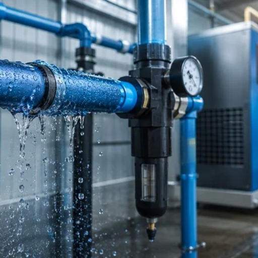
Water in compressed air lines after a dryer has several possible causes. Check liquid removal, untreated bypass air, drying performance and colder downstream piping. Find the first wet point, then check pressure dew point and drainage while the fault is present.
A running dryer makes the problem confusing. Its power light may be on, its display may look normal, and a machine across the building may still collect water. Replacing the dryer before checking that air path can leave the real cause untouched.
This checklist helps maintenance staff and plant engineers choose the next observation or measurement. It separates visible checks from service work and explains what each result can establish. You don’t need to guess a universal drain setting or buy a larger dryer to begin collecting useful evidence.
Key takeaways
- Map water in compressed air lines from the dryer outlet to the affected machine; one wet branch calls for a different investigation from plantwide symptoms.
- Measure dew point at a recorded pressure. A temperature display or warm outlet pipe doesn’t prove delivered dryness.
- Check the complete liquid-discharge route and untreated-air paths before blaming dryer capacity.
- Compare actual load and temperatures with the exact model’s limits, then repeat measurements under the original fault conditions before closing the investigation.
Triage water in compressed air lines before changing parts
First establish that liquid is inside the air system. Moisture on a pipe’s outside surface can be room-air condensation; it does not establish water in compressed air lines. Record whether the evidence came from a filter bowl, an approved drain outlet, a tool or the process itself.
Sketch the route from the compressor through the aftercooler, separators, receiver, dryer and distribution branches. Include bypasses and connections to other compressors. Our guide to compressor, dryer and receiver arrangement provides background, but use the installed arrangement for this investigation.
Record when water in compressed air lines first appeared. Note any recent change: maintenance, a new machine, a reopened valve, colder weather or a hotter compressor room. These are clues, not proof of a cause.
If water in compressed air lines has prompted an equipment inquiry, send your operating readings and system sketch, including the dryer model and where the water appears. That information gives the discussion a firmer starting point than compressor horsepower alone.
| Observation | Next check | Provisional meaning | Next action |
|---|---|---|---|
| Several outlets became wet after service | Trace bypass and parallel connections | Untreated air may be mixing in | Verify routing and valve condition |
| Water appears directly after treatment | Check drainage and valid outlet dew point | Liquid removal or drying may be inadequate | Follow the matching branch below |
| One remote machine is wet | Compare local pressure, temperature and dew point | A local condition may matter | Inspect that branch before replacing central equipment |
| Water appears during hot, busy shifts | Log inlet conditions and dryer flow | Capacity or cooling may change with load | Check the exact manufacturer’s limits |
Keep the first checks nonintrusive. Use only approved test points and functions. Before opening housings or changing pipes or drains, qualified staff must isolate, lock out and depressurize the equipment as its procedure requires. A stopped compressor can still hold pressure.
Measure pressure dew point when water in compressed air lines persists
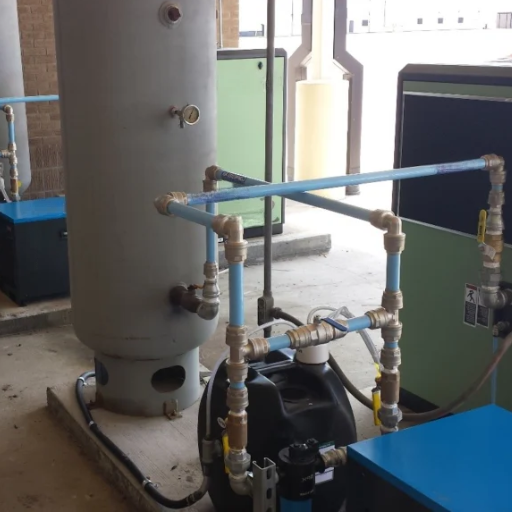
Pressure dew point, or PDP, is the temperature at which water vapor starts to condense at the stated pressure. Compare it with the coldest downstream air at that pressure. Air that cools below its dew point can form liquid even after a working dryer.
Check what the display measures
When checking water in compressed air lines, read what the display measures in the manual. A cooling temperature reading may not measure moisture directly. Touching the outlet pipe cannot measure PDP either. Refrigerated dryers may reheat air after removing moisture.
Don’t compare a dew-point reading taken at room pressure directly with the specified PDP. Record sample pressure and whether it is gauge or absolute pressure. If pressure differs between sites, check how to compare the readings. The same temperature need not mean the same moisture level.
Collect a representative sample
Use a sensor and sample cell rated for the pressure and moisture range. Follow its instructions for flow, tubing and how long to let the reading settle. Keep the sample route short and free of leaks. Water must not condense in the sample line before it reaches the sensor.
Take readings at the dryer outlet and affected machine while water in compressed air lines is present. Keep the records comparable. A quiet morning check cannot test a wet-air fault that occurs at the afternoon production peak.
| Record at both locations | What to write down |
|---|---|
| Location and time | Exact sample point, time and whether water was present |
| Operating state | Machines running, compressor/dryer state and airflow reference basis |
| Pressure and moisture | Sampling pressure, gauge/absolute basis, PDP and instrument identity |
| Temperature | Air-temperature measurement location and method; nearby cold zones separately |
| Sample quality | Cell, tubing, flow, stabilization and calibration status |
| Related observations | Drain discharge, alarms and recent valve changes |
High outlet PDP calls for checks of the sample, operating conditions and dryer. If outlet PDP meets the requirement but water in compressed air lines remains local, look downstream. Trapped liquid or untreated air mixing in may still explain it. If readings conflict, check the sample again before buying equipment.
The following Vaisala video shows spot checking and logging with specific instruments. It helps explain the measurement task. Follow your own instrument’s instructions for the actual test.
Trace bypass paths, separators and condensate drains
Water in compressed air lines can persist when the dryer cools air, but the separated liquid cannot leave. Drying and drainage are connected jobs, yet one can fail while the other appears normal. Kaeser’s dryer maintenance guide discusses drains, heat exchangers and controls as separate maintenance checks.
Follow untreated air and collected liquid
To trace water in compressed air lines, compare the actual air route with your sketch. Include maintenance bypasses, parallel dryers and links to other supplies. A closed handle does not prove that a valve seals inside. Qualified staff must test suspected leakage or routing with the site’s approved procedure.
Next, find each liquid collection point: aftercooler separator, wet receiver, prefilter and dryer separator where fitted. Record each drain and where its discharge goes. If water in compressed air lines begins here, note visible kinks, discharge routing and alarms. Do not disconnect parts under pressure.
Observe an approved drain test if the manual permits it. Does liquid reach the intended destination, or is there only a click, lamp or air sound? Those observations are different. Drain actuation alone cannot demonstrate that the whole liquid path is clear.
No discharge does not prove a blockage. Low load or good upstream liquid removal may leave little water at that drain. When water in compressed air lines accompanies a dry drain, compare both observations. Check load history, upstream drains and the exact drain’s instructions before choosing a fault to test.
Illustrative scenario: A team finds water in compressed air lines just after a refrigerated dryer. The temperature display looks normal. The drain clicks during its approved test, but the team cannot confirm liquid at the discharge point. This calls for a drainage-route check, without proving a blocked drain or a healthy cooling circuit.
Give the service team the location, load state, display meaning and drain observation. After safe isolation, it can test for a restriction. Record what it finds rather than treating the suspected cause as a fact.
Separate droplets from vapor
A liquid separator or coalescing filter addresses droplets within its intended operating conditions. It does not replace the vapor-removal function of a dryer. Parker’s guide to drying compressed air explains this distinction between liquid filtration and drying.
If discharge looks oily, don’t identify it by appearance alone. Oil and water in compressed air lines can coexist. The separate guide to screw-compressor oil carryover addresses that investigation; an air/oil separator is not a substitute for air drying.
Check dryer load, cooling and regeneration against the manual
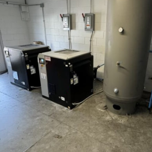
If water in compressed air lines persists after sample and routing checks, compare actual conditions with the dryer’s manual. A nameplate flow match does not prove capacity at every temperature or pressure. Record total flow through this dryer. Include machines that run at the same time.
Refrigerated dryers: compare the hot shift with the rating
Log inlet air temperature, pressure, airflow and cooling conditions while water in compressed air lines appears. For an air-cooled dryer, check accessible air paths and the condenser as the manual permits. For a water-cooled dryer, record the specified cooling-water conditions. Use the checks for that model.
Check alarm history and fan operation through approved observations. Leave refrigerant pressures, electrical faults and sealed-circuit work to trained service personnel. There is no model-independent thermostat setting that this checklist can safely prescribe.
Illustrative scenario: A workshop adds a machine, then finds water in compressed air lines only on hot afternoons. The dryer’s nominal flow rating seems sufficient. Compare peak flow, hot inlet air, cooling conditions and minimum pressure with the model’s corrected capacity. Use readings from the wet shift.
If corrected capacity is too low, check sizing. If capacity is adequate, test cooling, drainage, controls and the sample method. Heat and water in compressed air lines occurring together tell you when to test. They do not identify a failed part.
Use our published guide to size a dryer with manufacturer correction factors for that calculation. Keep the same flow reference basis throughout. Do not mix actual-volume flow at line pressure with a rated free-air or standard-volume figure without a valid conversion.
Desiccant dryers: look across the operating cycle
If water in compressed air lines appears after a desiccant dryer, log PDP and alarms through a full operating cycle. One good reading can miss a later rise. Compare valve switching and regeneration with the manual. Check that the required upstream filters and liquid protection work.
Possible causes include restricted purge, switching faults, contamination and poor regeneration. One wet sample cannot identify which applies. Don’t force a tower change or set purge from a generic percentage. Give the service team the full cycle log, pressures and exact alarms to guide their tests.
Inspect cold branches and water trapped downstream
If outlet readings meet the requirement but water in compressed air lines affects one area, follow that pipe route. Look for exposed pipes, unheated rooms, low points, takeoffs and untreated connections. Compare readings from the same operating state. Account for different pressure zones.
Ask whether the branch becomes colder than the delivered PDP
A working dryer may not dry air enough for a colder branch. Cold weather can help explain local water in compressed air lines. Room or pipe-surface readings can flag a cold zone, but may differ from the air temperature inside. Use a suitable method to confirm the air condition.
Illustrative scenario: Assume air at 7 bar gauge has a measured PDP of +3°C (37°F), then cools to +1°C (34°F) in an exposed branch at the same pressure. These are teaching inputs, not plant readings.
The branch crosses below the assumed dew point, so condensation is possible. Actual diagnosis still needs valid readings and checks for trapped liquid or untreated mixing.
If the required PDP is below the installed dryer’s capability, review air dryer types and pressure-dew-point selection. A larger liquid trap alone cannot lower water-vapor content to meet a colder-air requirement.
Account for standing water after a repair
Water in compressed air lines can remain in low points or receivers after a repair. Qualified staff should locate and clear it with approved procedures after isolation. There is no fixed dry-out time. Pipe layout, stored liquid and operating conditions all matter.
Do not label continuing water as residue without checking whether new liquid is still arriving. Repeat dew-point and drainage checks, then inspect the local route. Our compressed-air distribution layout guide provides broader design context; this checklist stays focused on locating the present wet-air fault.
Point-of-use liquid protection may help manage droplets while the cause is investigated. It does not establish that the air meets a process moisture requirement. If the evidence does not fit cold piping, drainage or bypass mixing, document the contradiction and investigate other local entry paths.
Prove the fix and prepare a useful service handoff
Define success before closing the fault investigation. Use the written process moisture limit and dryer specification. Account for the coldest expected downstream condition. A dryer type alone does not prove a purity class; moisture results also cannot prove particle or oil quality.
Repeat readings at the original sample points. Record pressure, time and load. Recreate the condition that exposed water in compressed air lines: peak demand, a cold branch or a regeneration change. A dry sample under easier conditions cannot show that the original fault is resolved.
Close the evidence gaps
The handoff should let another person follow the reasoning without relying on memory. Attach these records, marking anything still missing:
- Dryer model and the relevant manual page.
- Air-path sketch with bypasses and wet locations marked.
- Before/after pressure, PDP, temperature and load readings.
- Sample method, instrument and calibration record.
- Drain observations, alarm history and completed repair details.
Separate each observed change from its proposed cause.
For example, record that liquid discharge resumed in an approved test after a documented repair. That alone does not prove the downstream moisture limit is met. For water in compressed air lines, verify the repair with use-point readings against the requirement.
Confirm that trapped liquid has been removed or accounted for and check whether fresh liquid continues to appear. Recheck the complete system if the remaining pattern changes. Two faults can coexist, so improvement after one repair does not make every other observation irrelevant.
If readings disagree, revisit location, pressure basis, timing and sample quality before changing another component. Do not close the issue solely because the dryer runs, a repair ticket is complete or an operator reports one dry shift. The acceptance evidence should match the original symptom and the written requirement.
For an equipment discussion, send the model, airflow basis, temperatures, pressure, required PDP and measured result together. This connects any proposed change to actual operating limits. It also shows the gaps in the evidence before you compare dryers. Missing data should remain visible in the handoff.
Questions about water after an air dryer
Why is there water in compressed air lines when the dryer is running?
A powered dryer can still pass wet air if drainage, bypass routing, drying capacity or regeneration is inadequate. Water can also form farther downstream where air becomes colder than its dew point. Locate the first wet point and obtain a valid outlet PDP measurement before deciding which mechanism applies.
Does a dryer that is not draining water always have a blocked drain?
No. There may be little liquid to discharge, effective upstream drainage, a control fault or a restricted discharge path. Use the model’s approved test and compare the observation with load and operating history. A clicking valve does not prove liquid flow, and absent water does not prove blockage.
Why is water in compressed air lines limited to one room?
A cold section, low point, untreated connection or trapped liquid may explain it. Compare dryer-outlet and local readings while the fault is present. Record pressure at each point. Inspect the branch route and drains before blaming the central dryer or assuming a local filter will solve the fault.
Will an extra filter remove the remaining water vapor?
A separator or coalescing filter removes liquid droplets within its design limits; it does not perform the same job as a dryer removing water vapor. If vapor condenses farther downstream, check delivered PDP against local conditions. Additional liquid protection may manage droplets without resolving the underlying drying requirement.
Should I replace the dryer with a larger model?
Only after checking its actual operating envelope and excluding other causes. Compare peak flow, inlet temperature, pressure and cooling conditions with the exact manufacturer’s capacity procedure. A larger unit does not correct an untreated bypass, a failed discharge route or a drying technology unable to meet the required PDP.
Choose the next action from the readings. Locate water in compressed air lines, validate the sample, trace drainage and bypasses, then check operating limits and cold branches. Repeat the checks where the problem occurred before closing the job. If you are considering equipment changes, contact Loyal with your model, readings and system sketch. Include the required use-point moisture condition as well as the measured result, so the inquiry describes both the present problem and the performance you need.