
Compressed Air Condensate Drains: Troubleshooting No Drainage and Continuous Air Loss
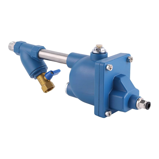
When compressed air condensate drains stop discharging, trace the liquid path. Check whether water reaches the drain, the valve opens and the outlet is clear. When air keeps escaping, find the outlet and control type first. Then check for a stuck valve.
A click is useful evidence, but it doesn’t prove that water can leave. A quiet drain may have no liquid to remove. A test can pass while automatic control still fails. Those distinctions prevent a rushed parts order based on the wrong symptom.
This guide shows what you can observe and what needs a trained technician. Follow the branch that matches what you see. Note what it proves. Use your model’s manual for the next check.
Key Takeaways
- Distinguish no discharge, discharge only on test and sustained air loss.
- Identify timer, float or electronic level control before judging normal operation.
- Trace both the liquid feed and discharge route; a working valve cannot fix bad piping.
- Verify automatic drainage and closure after service, then assess any remaining wet-air problem separately.
Planning an equipment inquiry? Send Loyal the model, operating pressure and drain observations, including where the drain sits in the system.
Identify compressed air condensate drains before testing
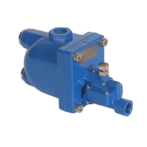
Locate compressed air condensate drains at the receiver, aftercooler separator, filter bowls and dryer collection points. Give each drain an identifier on a sketch. The compressor, dryer and receiver arrangement guide can help you recognise the equipment layout, though the installed piping still needs checking.
Match the mechanism to normal behaviour
Compressed air condensate drains do not all open for the same reason. Timed compressed air condensate drains follow a set interval. Float types respond to liquid level. Electronic types use a sensor and controlled valve.
Some designs also need enough pressure to work.
| Control type | What normally initiates discharge | What silence or air noise cannot prove |
|---|---|---|
| Timer | A scheduled opening | Whether liquid was present for that event |
| Float | Liquid moves the float mechanism | Whether the float is free or the feed is clear |
| Electronic level | A sensor detects collected liquid | Whether the sensor, valve and liquid path all work |
Brief air release may accompany a timed event. Level-controlled designs aim to discharge collected liquid without needless air loss, but their alarms and test modes differ. Read the indicator and alarm definitions for your device rather than copying another drain’s timing.
The official BEKO animation below illustrates a level-controlled drain. It is an operating concept example, not a service procedure or a claim that Loyal supplies this brand.
A timer can open even when there is no water. A float may stay still until enough water collects. With a sensor drain, check which light means power and which means a fault.
Keep observation separate from dismantling
Observe only from a safe position using the site’s approved procedure. Do not remove a bowl, loosen a fitting or open the electrical enclosure to investigate a live system. A trained technician must isolate the equipment, cut power and release pressure before service. They must check for stored energy before work starts.
Illustrative scenario: An operator hears a burst near a desiccant dryer and records a drain leak. Tracing the physical outlet identifies regeneration exhaust instead. The next step is to compare that exhaust with the dryer manual, rather than ordering a drain valve from the sound alone.
Compressed air condensate drains with no drainage
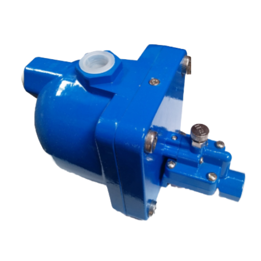
Start with one question: should liquid reach this drain under the conditions observed? Compare the collection point with upstream removal, current air demand and the normal wet shift. Less use or drier intake air can mean less water. Silence alone does not prove a blockage.
For compressed air condensate drains, keep four observations separate: no liquid available, no apparent actuation, actuation without discharge and discharge only during a test. Each points to a different investigation.
Use the symptom to choose the next check
| Observed result | Possible explanation | Next authorised check |
|---|---|---|
| No discharge during a quiet production period | Little liquid arriving, or an interrupted feed | Compare load and upstream drainage; inspect the visible feed route |
| No response to the permitted test | Control/supply fault, or a device outside its conditions | Record indications; have a technician check the exact manual and supply |
| A click, but no liquid leaves | No liquid, obstructed piping, valve fault or pressure issue | Check liquid availability, feed/outlet route and operating pressure |
| Liquid leaves only during test | Automatic sensing or feed/collection problem | Record the result separately; investigate automatic operation |
These are possible causes. They aren’t a parts list. The BEKOMAT 32U manual, revision 01-1611 v01, page 24, separates no discharge, test-only discharge and continuous blow-off. It lists feed/discharge obstructions, service-unit faults and pressure limits among the checks for that model.
A power light or click is only partial evidence
On compressed air condensate drains, a lamp may show the supply or a documented control state. It does not confirm a clear liquid path. A click doesn’t show that the valve fully opens. Nor does it prove that pressure can move water through the outlet.
Where the manual permits a test button, record the actual result: indication, sound, liquid discharge and whether flow stops. Do not copy a button-hold duration from another device. Don’t keep pressing test to clear an alarm. You may hide the fault you need to record.
Compressed air condensate drains that work only on test need their own fault record. On this BEKOMAT model, feed slope, feed size, surges and a dirty service unit are possible causes. The Omega RDP troubleshooting guide also identifies a dirty capacitive sensor for its test-only symptom. Neither list proves a sensor fault in every drain.
Illustrative scenario: A receiver drain empties upstream while a dryer drain remains quiet during low demand. The operator notes both locations. They follow the approved procedure to observe a period of normal loaded use. This avoids calling the second drain blocked solely because its neighbour discharged first.
Escalate wet-air symptoms on their own evidence
If drainage is restored but downstream water persists, review air dryer types and pressure dew point. Drainage removes collected liquid; drying addresses water vapour. One drain event doesn’t prove that air meets the process needs.
If the problem occurs during a hot, humid shift, record inlet conditions and demand then. Where evidence points to dryer overload, use manufacturer correction factors for dryer sizing. Do not increase dryer size simply because one drain stays quiet.
Compressed air condensate drains that lose air continuously
First establish whether the air comes from the drain outlet, a nearby fitting, an unloader or dryer regeneration exhaust. Listen from a safe position and trace the route on the layout. Avoid placing a hand over a discharge to identify it.
With compressed air condensate drains, timing matters as much as sound. Record whether air flows only during intended events, continues after liquid clears or appears in repeated alarm cycles. Compare that pattern with the controller manual.
Separate expected events from sustained flow
Timed compressed air condensate drains can release air during the opening period. A level drain can have a distinct test or alarm response. An unexplained stream that won’t stop still needs checking. Note whether the valve should have closed and whether the flow stops between events.
The Omega Air RDP 20-1900 troubleshooting guide, printed on page 2, lists a dirty diaphragm and sensor components among possible causes of air at its drain outlet. The BEKOMAT 32U manual lists a dirty or defective service unit for continuous blow-off. These examples show why valve design matters. Find the model before you choose a repair.
Do not diagnose compressed air condensate drains by noise alone. Other compressed air condensate drains may use different parts, and an apparent continuous leak may actually be a repeated commanded event. Record the control state and actual flow together. This helps the technician tell the causes apart.
Do not stop the symptom by defeating drainage
Capping the outlet, disabling alarms or leaving an operating collection point isolated can retain liquid upstream. Lengthening a timer interval may reduce the sound without correcting why a valve fails to close. Use the site’s approved equipment procedure for any short-term change.
Illustrative scenario: A filter drain keeps venting after visible liquid clears. The operator records the outlet, duration and controller state. A trained technician takes the equipment out of service under procedure. They check the assembly listed in its manual.
Dirt is only a suspected cause until they find it.
For compressed air condensate drains, a useful record includes the state before the event, the liquid/air sequence and the state afterwards. A short sound recording from a safe spot may help show timing. It can’t reveal the valve’s internal state or measure the leak rate.
Don’t claim a savings rate without leak measurements and plant operating data. The immediate goal is restored drainage and closure. Add follow-up observations to the plant log so recurrence is visible at the next shift handover.
Trace the inlet, outlet and condensate collection route
A working valve cannot drain liquid that cannot reach it. Sketch the full path: collection point, service valve, feed pipe, drain body, discharge pipe and receiving system. Use the compressed-air distribution layout guide for system context, then compare the actual branch with its equipment manual.
Compressed air condensate drains need both an adequate feed and a suitable outlet. Look for visible kinks, unsupported hose, low pockets, upward sections and changes made since the system last worked. Use what you see to choose the next check. It won’t prove what is inside a pipe.
Check pressure and routing together
Pressure at compressed air condensate drains may differ from the compressor display. Closed valves and pressure differences between collection points and the discharge route can affect operation. A trained technician should measure at approved points. They can then compare pressure with the model’s limits.
For a concrete example, the cited BEKOMAT 32U manual gives an operating range of 0.8-16 bar on page 7. Its installation section also changes minimum pressure requirements when the outlet rises. Those are model-specific conditions, not universal operating settings or a formula for another drain.
Do not connect separate collection points to shared compressed air condensate drains simply because the hoses reach. The BEKOMAT installation guidance warns about pressure differences and feed arrangements. Each point needs the drain setup specified for its equipment. An improvised link can disrupt the liquid path.
Do not assume every drain needs an added strainer
Installation advice for compressed air condensate drains is design-specific. The cited BEKOMAT 32U manual prohibits a filter or screen in its feed line. By contrast, JORC describes an integrated strainer on its KAPTIV-CS design. Identify the model before applying either instruction.
When servicing compressed air condensate drains, use the installed manual to check what may be cleaned, removed or replaced. Adding an external screen to a design that forbids it is not a general fix for dirty condensate. Nor does one model’s restriction authorise removing a supplied strainer from another.
Follow the discharge route to its destination as well. Do not discharge into an improvised closed container or assume ordinary waste plumbing can accept pressurised flow. Use the specified collection and treatment arrangement, and check applicable local disposal requirements for potentially oily condensate.
Compressed air condensate drains are one part of that route. Restoring their valve function does not establish that downstream treatment works or that disposal is permitted. Include the receiving arrangement in the handoff if backpressure, blockage or unsafe collection remains possible.
Verify automatic operation after service
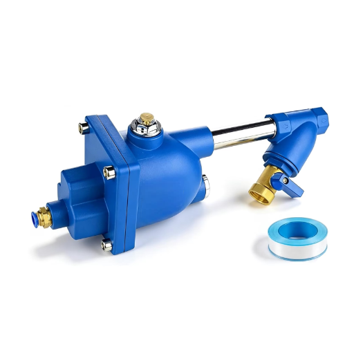
Use the exact manual, matching parts and trained staff for service. Record what was found, what was changed and what is still unknown. A cleared alarm or a test button result isn’t the end of the job.
For compressed air condensate drains, verification must include automatic collection, discharge and closure under representative conditions. The Atlas Copco dryer maintenance checklist reinforces checks for standing water and continuous air loss, while separating routine observation from specialist work.
Start by writing the fault in plain words. For example, distinguish a valve that never opens from one that opens only on test. Add the actual service work and any changed parts to the log. This lets the next shift compare like with like.
Keep a before-and-after record
| Record field | Before service | After service |
|---|---|---|
| Drain identity and manual | Model, location and revision | Confirm the same equipment was checked |
| Conditions | Pressure, demand and wet/hot shift context | Note whether conditions were comparable |
| Control behaviour | Lights, alarm, timer or test result | Record automatic response, not just reset |
| Liquid path | Known arrival and discharge observations | Confirm liquid leaves through the intended route |
| Closure | Sustained flow or event timing | Record whether unwanted flow stops |
If there is no water during a short visit, say so. Don’t record an automatic cycle that you haven’t seen. Arrange a check during normal use. Keep the fault open until you can verify that function.
Bring compressed air condensate drains into the routine oil-injected compressor maintenance checks. Use the drain OEM’s service schedule for that component rather than borrowing a generic interval from the compressor.
Return to the illustrative filter-drain example: after service, the useful result is observed automatic discharge followed by closure. A quiet outlet alone doesn’t prove the feed is open. If pressure dew point or downstream liquid remains outside the process requirement, investigate that separate condition before calling the whole air-treatment system healthy.
Questions about condensate drain faults
Does no water discharge always mean a blocked drain?
No. Little liquid may be reaching the drain because load is low or upstream equipment has already removed it. A closed feed, control fault or pressure issue is also possible. For compressed air condensate drains, compare the collection point and operating conditions before treating silence as evidence of blockage.
Why does the valve click but no water comes out?
A click may mean the valve received a command. It doesn’t prove full movement or liquid flow. There may be no water available, an obstructed feed or outlet, or unsuitable pressure. Record what happens during the permitted test, then have the route and device checked against the exact manual before replacing parts.
Why does the drain work only with the test button?
A test can open the valve while automatic sensing or collection still fails. Manufacturer examples include dirty sensors, feed restrictions and surges, depending on the design. Compressed air condensate drains need an automatic-operation check after service; repeated manual testing is not a substitute for diagnosing that separate fault.
Why does an automatic drain keep blowing air?
Possible explanations include an intended timed event, alarm behaviour or a valve assembly that fails to close. Confirm the physical outlet and the event pattern first. The cited manuals identify dirty or defective parts for particular models; that does not establish the cause in an unidentified drain.
Can I use one timer setting all year?
Do not assume one setting suits every season or load. Condensate production changes with operating conditions, and the timer must suit the installed drain and application. Follow its adjustment procedure and verify drainage and closure during representative demand, especially when the reported problem occurs on a hotter, more humid shift.
For an equipment discussion about compressed air condensate drains and their place in your system, contact Loyal with the model, drain location, pressure and symptom log. Start with the observed fault, trace the liquid route and then verify automatic operation. Send measured facts and note any check still pending.