
Air Compressor Installation Requirements: Complete Factory Guide

A food processing plant in Thailand installed a 75 HP screw compressor in a converted storage closet. The room had no windows, no exhaust fans, and no ventilation plan. Within 18 months, the air bearings failed from chronic overheating. The repair cost 8,400. Lost production cost another 12,000. The fix was two 24-inch exhaust fans and a louvered intake vent, with a total cost of 220. A220 ventilation upgrade would have prevented a $20,400 failure.
You have already done the hard work of selecting the right compressor. You compared screw vs piston technology, sized your CFM and horsepower requirements, and chose between VSD and fixed speed. Now comes the phase that determines whether that investment performs for 15 years or fails in 18 months: installation.
This guide covers the exact air compressor installation requirements for industrial factories. You will find electrical sizing tables, ventilation CFM formulas with worked examples, concrete foundation specifications, piping pressure drop guidance, and compliance checklists for major markets. Whether you are installing a 10 HP piston unit or a 200 HP rotary screw system, these requirements apply.
Want more information? Our complete guide on how to choose an air compressor for your factory covers the full selection framework from demand audit to total cost of ownership.
Pre-Installation Planning Checklist
Installation starts weeks before the compressor arrives. The planning phase prevents the costly surprises that derail commissioning.
Please check the amount of air required to run the equipment and the type of compressor the company supplies you with by making a call. Then, match the CFM you have obtained with the compressor’s free air delivery at your designed pressure. Look at the electrical systems to ascertain the voltage, phase, and full-load amperes. Plus, step around your building to cross-check the physical measurements of your room against the necessary clearances. Also, make inquiries about obtaining approval for the factory. There are limited fees which are applicable in enabling these permits that are necessary in the installation of three-phase devices. Some other jurisdictions require mechanical permits or even conduct fire safety inspections, even for the electrical equipment.
Want installation support tailored to your site? Contact Shandong Loyal Machinery for a pre-installation assessment and room layout recommendation.
Space and Location Requirements
Minimum Clearance Distances
Manufacturers establish minimum tolerances for a variety of reasons: accessibility for servicing, air flow and heat removal. If you violate these requirements, be prepared to be left out of the warranty and damaged equipment.
| Location | Minimum Clearance |
|---|---|
| Rear of compressor (cooler access) | 3 feet (0.9 m) |
| Front of compressor (service panel) | 3 feet (0.9 m) |
| Sides (airflow and filter access) | 2 feet (0.6 m) |
| Overhead (crane or lift access) | 2 feet (0.6 m) above tallest component |
| Between multiple compressors | 4 feet (1.2 m) minimum |
| Air-cooled compressor intake | Clean, unrestricted wall or outdoor source |
These are minimums. In tropical areas or for equipment that’s continuously operated, maintain 50% additional headgroom. A compressor room which is undersized may entail greater workforce effort in repair and replacement of components more than the purpose it is built for.
Environmental Conditions
The design of compressor rooms is such that they retain the specific temperature of 40°F and 100 °F. If the temperatures are below 40 °F, there is a possibility that condenser water freezes in the dust and flow and control lines. On the other hand, if the temperature rises above 100 °F, the lubricating oil ceases to perform its mechanical function effectively and exposes the motor to the danger of losing its insulation. Relative humidity shall be 80% maximum to do away with electrical corrosion and water vapor penetration to the airend.
This requires a clean environment. The dust, foreign vapour and abrasive particulates every time the compressor inhales air quicken the wearing off process and the pollution of lubricating oil. Given that you produce such irritating substances, the air duct systems would always be taking in clean and external air, but it would be inappropriate to get air from the plant floor.
Altitude Effects
The higher the elevation above sea level, the less dense the air becomes by roughly 3% per every 1,000 feet. A compressor that provides 500 CFM of compressed air volume at sea level is capable of producing roughly 455 CFM of air at 5,000 feet above sea level. In the event your business is also located at a high altitude, use an additional safety margin when calculating the size of the compressor or instead check the manufacturer’s correction slope for operation altitudes.
Need to design an Air compressor system for your production line? Check out our article on Compressed Air System Design for Production Lines.
Electrical Requirements and Sizing
Mistakes during installation in areas of electrical work tend to be the most common among all operations and are required to be understated. Devices that are proposed sometimes fail since they can not handle the load placed in them. The wires specified in the design overheat with a lot of ease. Faulty grounding is dangerous. Take steps to prevent the need for maintenance due to electrical upgrades or adjustments.
Single-Phase vs Three-Phase Power
Small piston and scroll air compressors up to around 10 HP can be powered using 230V single-phase voltage. For piston and scroll air compressors having motor power in the range of 10 HP and above, 400 to 460V three-phase current is essentially required. Also, the industrial experience shows that 3-phase motors are more efficient and easier to start than single-phase motors.
Such 3-phase motors in industrial applications last much longer than single-phase motors. Should there be no installation of 3-phase electricity done at the establishment, check with the power provider prior to installing and buying a compressor that is larger than the existing one. The cost of fitting a three-phase electric supply at a building may get much higher than the cost of the compressor itself.
Grounding and VSD Considerations
Each one of the motors of the compressor frames should be connected to the ground as per the instructions of the local code. More requirements that apply especially to VSD-driven variants include: the use of input line reactors or DC bus chokes to reduce the distortion of harmonics, proper screening of the control cables and a maximum imbalance of the line-to-line voltage of ±3%. Any three-phase voltage unfettered causes VSD protection trips and control cards to fail within a year.
Ventilation and Cooling Requirements

Let’s remember that compressors are nothing but heat machines. In the case of helical screw air pumps, only around 20% of the energy that was bought as electric power leaves in the form of compressed air. The rest as much as 80% to 85%, is now an extra heat. When such heat is retained within the room, it causes a rise in the room’s temperature, leads to degradation of the oil and ultimately component failures.
Heat Output Calculation
The devices that are utilized to compress that air account for the generation of 2545 BTU per hour for each hp of the motor that is applied. With a 50 HP compressor, one can now visualise around 127,250 BTU/hr. Thus, in this compressor, you will have a basic industrial-sized furnace running continuously.
Ventilation CFM Formula
Use this formula to calculate required ventilation airflow:
CFM = BTU/hr ÷ (1.08 × Temperature Rise in °F)
For example, if the ambient room temperature is 70°F and outside air is 85°F, the temperature rise would be 15°F and would be acceptable.
Worked Example: A 75 HP compressor generates 75 × 2,545 = 190,875 BTU/hr. With outside air at 80°F and a target room temperature of 100°F (20°F rise):
CFM = 190,875 ÷ (1.08 × 20) = 8,837 CFM
This means that the compressor room needs about 8,800 m3 per second of ventilation air to be exhausted in the room. For this purpose two 36” exhaust fans with a capacity of 5,000 CFM each would deliver adequate air flow with some margin.
Natural vs Mechanical Ventilation
Natural ventilation through louvers works only when the building geometry creates sufficient stack effect and cross-ventilation. Most factories require mechanical exhaust fans with motorized intake louvers. Place exhaust fans high on the wall opposite the intake source to pull heat across the compressor and out. Never blow hot exhaust air directly onto another compressor or into an adjacent workspace.
Foundation and Mounting Specifications
When using rotating screw air compressors, the most important thing is to minimize vibrations and to provide a vibration isolation pump foundation, so the foundation must be solid, flat and leveled. A compressor installed on uneven or flexible flooring vibrates excessively, loosens fasteners, and in most cases damages the piping in such junctures.
Concrete Pad Requirements
With respect to compressor power, the thickness of this level will range from 6 inches to 12 inches, provided it is on grade and filled with either compacted gravel or engineered fill. A 4-inch industrial floor may be sufficient for small piston compressors with less than 10 HP. For rotary screw compressors 25 HP and above, it is advisable to have separate concrete floors to prevent them from vibrating the other floors
Make sure to lay up the cement base as defined in the section with 4-mesh of #4 rebar at 12-inch intervals in orthogonal direction. The dimensions of the pad must extend at least six inches more than the base of the compressor on all sides. Carry out the necessary steps to allow the concrete slab to develop until mature enough, i.e., at least seven days. The anchor bolts must lie towards the compressor base frame and should not be more than 1/8 of an inch off.
Anti-Vibration Mounting
Firstly, mounting pads and spring isolators should be introduced between the foundation and the compressor frame to eliminate vibrations. For compressors below 50 HP, 1/2 inches of neoprene pads are most of the times sought. Beyond the limit of 50 HP, add support of spring shock absorbers engineered for the operating weight and rpm of the compressor. When separated from the structure, the vibration of the compressor escapes the building and generates complaints from neighboring departments.
Compressed Air Piping Installation

Piping is the tortuous pathway that decides whether the compressed air produced reaches the intended location at the suitable pressure and quality. Inadequate design of pipes is one of the biggest enemies of compressed air systems as it results in unnecessary pressure drops and loss of energy.
Pipe Sizing by CFM and Distance
| CFM | Distance 100 ft | Distance 200 ft | Distance 300 ft | Distance 500 ft |
|---|---|---|---|---|
| 50 | 1.5″ | 2″ | 2″ | 2.5″ |
| 100 | 2″ | 2.5″ | 2.5″ | 3″ |
| 200 | 2.5″ | 3″ | 3″ | 4″ |
| 300 | 3″ | 3″ | 4″ | 4″ |
| 500 | 3″ | 4″ | 4″ | 5″ |
| 750 | 4″ | 4″ | 5″ | 5″ |
| 1000 | 4″ | 5″ | 5″ | 6″ |
These are straight runs with very few elbows so the following length would be acceptable. The proper size of fittings should be carefully determined and the design of accompanying auxiliary components. Piping system design should eliminate excessive flex hose and long pipe runs with no valves every 5-foot or less.
Loop vs Dead-End Distribution
A 60 HP compressor was installed in a Bangladeshi textile plant to supply the entire plant through a single 1-inch dead-end pipe. At full capacity, the pressure drop exceeded 15 psi. The compressor kept trying to make up for it by running all the time at maximum pressure, causing energy wastage, 18% beyond the required. Such an excessive consumption was substantially curtailed when a 2-inch loop main having appropriately dimensioned branches was connected. The energy consumption saving margin came up to $ 32,00 per annum and the annual cost of the piping and distribution system alterations was $ 900 and was cost-effective in less than 4 months.
Loop mains deliver air from two directions to each drop point, halving the effective travel distance. They also allow sectional isolation for maintenance without shutting down the entire plant. For any factory with more than three production zones or 200 feet of pipe run, design a loop distribution system.
Need help sizing your compressed air piping? Contact our engineering team for a piping layout recommendation based on your factory footprint.
Moisture Separation and Drainage
Compressed air is moist, containing condensate as a result of the cooling of the air flow in pipelines. Put moisture and promoters in the compressed air system in three places after the aftercooler post exit and on the lowest points in the layout. Make sure that water cannot stay in any of the devices by attaching auto-drain traps at various points. Where there is an oil lubricated compressor, please ensure that an oil-water separator is installed so that the drains containing water will not pollute the environment. Three things should be noted: compressed air condensate contains oil which is not easily directed off the premises in an environmentally acceptable manner.
Intake Air Quality and Filtration
A large amount of air is required by compressors. A 100-horsepower screw compressor can take in about 500 CFM. All the contaminants from that air go straight to your air compressor oil or compressed air system.
ISO 1217 Standard Intake Conditions
The performance of a compressor is measured against certain expectations of pressure at the inlet, which is typical in the industry. These are 14.5 psi air pressure 68°F temperature from the environment and no moisture content, that is, 0% relative humidity as in most industries. Intake of air that is warmed by a hot climate or contains a lot of water moisture will cause a decrease in efficiency and the addition of moisture. Whenever it is possible, for instance during the summer heat, route intake air through insulated ductwork from outdoors or other cooler areas and not from the compressor room.
Pre-Filtration Specifications
Typical compressor intake filters have a particle capture size of 10 microns. Special high-dust filters, with 3 micron grade and large filter area, should be installed when applications have a relatively dust-laden environment. Frequently, downtime is an emergency scenario and going 2000 – 4000 operating hours without checking the intake filter may be unacceptable in these situations. Dirty intake filters fouled with solids decrease system output by 3% to 5% and also increase power consumption.
Permits, Codes, and Compliance
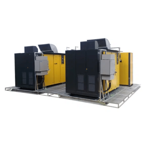
A 100 HP compressor should have been taught to the customer by a metal fabrication company in the Southwest without consideration of the electricity regulations in force. As was the norm, the contractor installed the compressor. In order to pass the local inspection, the compressor which was to be installed, needed additional accessories such as a dedicated transformer, a fire-rated room, and a number of extra emergency shutoff controls.
It became necessary to seek a permit modification which delayed the installation for 4 weeks and $4,500 in additional repairs were incurred. If adequate planning had been done during the initial stages of the site assessments, the need for all this would have been unearthed and accordingly addressed.
Permit requirements vary dramatically by jurisdiction. The table below summarizes typical requirements by region:
| Requirement | United States | European Union | China | India |
|---|---|---|---|---|
| Electrical permit | Required for 3-phase | Required | Required | Required |
| Mechanical permit | Varies by locality | Required in most countries | Required | Factory Act applies |
| Noise compliance | OSHA 90 dBA 8-hr limit | EU Directive 2003/10/EC | GB 12348 standard | Factories Act 1948 |
| Fire separation | May be required | Often required | GB 50016 compliance | NBC compliance |
| Environmental discharge | EPA oil-water rules | Local discharge limits | GB 8978 wastewater | CPCB norms |
| Pressure vessel registration | State boiler codes | PED compliance | TSGR0004 | Indian Boiler Regulations |
Also, make sure that you clarify the specific requirements before you begin the setup of your equipment with that provider. We recommend that you allow up to 2-4 weeks for building approval beyond the time it will take you to set it up.
Installation Cost Breakdown
It is possible to say that the installation of a small unit is from 15% to 30% of the price of the machine and from 10% to 20% for its industrial counterpart, its cost per electrical horsepower being more concise.
| Component | 10-20 HP | 25-50 HP | 75-100 HP | 150-200 HP |
|---|---|---|---|---|
| Electrical (panel, conduit, wire) | 500−1,500 | 1,500−3,500 | 3,000−7,000 | 7,000−15,000 |
| Ventilation (fans, louvers, ducting) | 200−800 | 500−1,500 | 1,000−3,000 | 2,000−5,000 |
| Foundation/concrete pad | 300−800 | 500−1,500 | 1,000−2,500 | 2,000−4,000 |
| Piping and fittings | 300−1,000 | 800−2,000 | 1,500−4,000 | 3,000−8,000 |
| Labor (installation and commissioning) | 500−1,500 | 1,000−2,500 | 2,0000−4,000 | 4,000−8,000 |
| Permits and inspections | 100−500 | 200−800 | 500−1,500 | 1,000−3,000 |
| Total Estimated Cost | 1,900−6,100 | 4,500−11,800 | 9,000−22,000 | 19,000−43,000 |
These are cost plans. The real cost may vary depending on the geographical area, the available infrastructure, and the complexity of the site itself. Factories that operate on three phase power and have looping circuits existing at the compressor location will experience lower costs.
Common Installation Mistakes
Insufficient ventilation tops the list of preventable failures. Inadequate airflow causes compressor discharge temperatures to rise 10-20°F above design, reducing oil life by up to 50% and accelerating airend wear.
Undersized electrical supply creates a different set of problems. Breakers trip under peak load. Motors overheat from low voltage. Contactors pit and fail prematurely. Size the electrical infrastructure for the nameplate full-load amps, not the average running load.
Inefficient pipe layouts consume excessive energy due to high-pressure drops. For every extra 2 psi of pressure drop, there is an additional 1% of input work for the compressor. A 10 psi drop in the pipe will add an extra 5% to your electric bill over a year.
Not considering appropriate access results in a half hour task to take out and change a 30 second filter, becoming a 2-hour ordeal. Pneumatic tool service should include activities such as opening panels, releasing components, and using tools. Should they not be able to operate, efficient costs due to regular maintenance are incurred and the machine is back in the line of service beyond normal period.
This inappropriate draining allows the accumulation of water in the lower regions. Full of air hoses may fail efficient air–handling devices due to water hammer. Insightful low-moisture treatment strategies will prevent the dew point of water from causing pipe walls to degrade. Fast flow of air can make the moisture levels in the air call dew point, which could then collect in a particular region, say in the case of cooling a cylindrical object with compressed air.
Post-Installation Commissioning Checklist

Before declaring installation complete, verify these items:
Electrical verification: Instantaneous Measurement of the pressure on compressor terminals and make sure that it is the same as written on the Identification Plate within a 5% range. Phase rotation checks, too. All compressors’ terminal connections should be torqued according to the insulation resistances to prevent further problems.
Air leak testing: Inflate the appliance to the maintenance pressure level required and run inspected pipes with the help of a water test. Any bubbles generated from the soapy water test are considered as a leak and will have to be reinforced.
Performance verification: Make remarks of actual pressure, temperature, and amps at full load discharge. Measure against manufacturer standards. Check for compressors where the unload pressure is reached and the pumpout starts operating.
Safety system checks: Do not forget to check emergency stop switches. Ensure a set of stop features, especially high temperature shutdown. Pressure relief valves must be ensured to be in the correct dimensions, fixed correctly, and tagged properly.
Frequently Asked Questions
What are the installation requirements for an air compressor?
The installation of industrial air compressors should have at least 3±ft clearance on the service sides, and will require proper electrical supply (three-phase 400-460V for units over 10 hp), mechanical ventilation to remove the waste heat created by the equipment, a level concrete foundation, appropriate sizing of the compressed air piping, and adherence to local regulations including the electrical codes and permits.
How much clearance does an air compressor need?
For clearance purposes, the market provides air compressors with clearance of 3 feet at the front and rear for service access, 2 feet on the sides and 2 feet overhead. When two or more compressors are being installed, space of 4 feet must be left between the units. Increased clearance should be allowed in hot conditions and continuous-duty applications.
What electrical connection does an air compressor require?
It is common that air compressors of 10 HP and lower are powered by single-phase 230V. On the other hand, air compressors of more 10 HP within the same light section will need a three-phase power rating of about 400-460V. The size of the overload and low voltage protection devices should be 125-150% of the full load current. Power gauge sizing shall respect distance and voltage drop factors.
Does an air compressor need a dedicated circuit?
Certainly. Dedicated circuits with no overloads other than properly sized breakers must be used for industrial compressors. When on shared circuits and there are other equipment loads within the same circuit, this will contribute to voltage drop during the start of the compressor, possibly leading to motor and control damage.
Conclusion
The importance of proper installation should not be underestimated or left to last minute. It affects the lifespan of the compressor—whether it’s able to work for 60,000 hours or fails after just 15,000. The five major criteria are: adequate space and working area, power supply to the compressor, heat extraction with sufficient, properly sized plumbing, the surfaces of whose structures remain stationary, the devices are properly leveled, and the looped circuit takes away condensate with the right delivery head.
Clearly, these results provide that improper installation accounts for more than 40% of all premature failures of the indicated compressors. The largest percentage other than failure due to defects, wear and tear, or any particular reason is installation errors, which fortunately, the majority of them were caused by ignorance of the proper procedures.
Before proceeding to a new compressed air machine, contact Shandong Loyal Machinery and they will provide you with a free installation evaluation. Their engineers offer suggestions on the location of the equipment in the room, their electrical capacity needs and pipe schema to ensure that your compressor runs efficiently right after it has been installed.